-40%
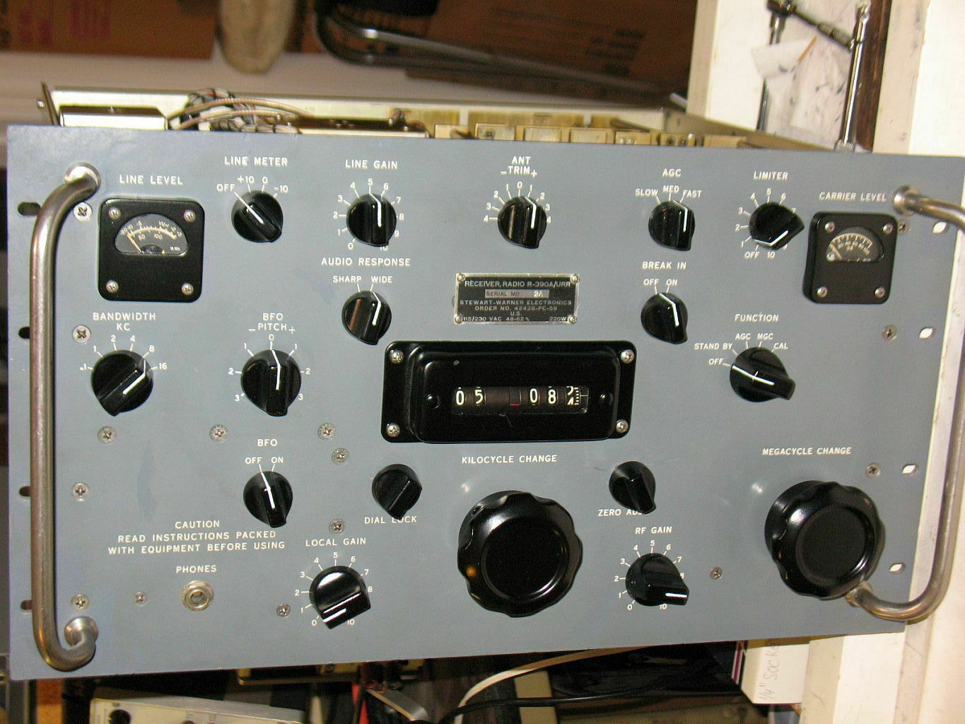
Collins designed R-390A Receiver mfg by Stewart Warner, refurbished, guaranteed.
$ 1108.8
- Description
- Size Guide
Description
This listing is for an R-390A receiver designed by Collins for our military for the HF bands and built by Stewart Warner in 1959. They were manufactured by numerous different manufacturers from 1954 through 1984. The reason so long - it's an awesome receiver. They receive AM, CW, and SSB from .5 Mh to 32 Mh in 32 calibrated bands and are extremely sensitive, selective (reject strong adjacent stations), stable, quite accurate, reliable and signal overload resistant. The original design did not provide good SSB reception, but with the very simple and easily removable modification I've installed, it now receives all strengths of signals excellently without adjusting the RF gain, using the BFO (Beat Frequency Oscillator). These change the AGC circuitry similar to Dr. Lankford's very popular 2 diode change to account for strong SSB signals, but does not degrade weak AM signal reception as the original change can. More on SSB reception later. All hardware (screws, nuts, washers, etc) is in excellent condition. As you can see from the pictures, the front panel face looks very nice (except for a little damage on the upper and lower left corners (which has been touched up so it's not hardly noticeable)) and all the lettering is excellent. It is an original engraved panel and has been touched up in a few places, but is very hard to tell unless you look very closely. The 17 knobs, meters, and dial readout cover have been refinished with 4 coats of Rustoleum Pro High Performance satin black spray paint that is very durable. The white lines on the knobs were done with Folk Art 4001 Wicker White enamel. These knobs should last for a very long time and they look very good. Please review all pictures carefully. As you can see, this unit has three fuses on the back instead of 1 fuse in the original design and manufacturing run. The additional 2 fuses were added a few years later and are very beneficial in preventing damage to important components and for trouble shooting. The correct 3 fuses are installed. The 2 audio output screw terminals on the back are 600 ohms. A matching transformer needs to be used if you are using a standard 4 or 8 ohm speaker. Two kilo ohm head phones can be used in the Phone jack on the front.I've been using this regularly for listening for the last 11 months and it is very reliable, stable and works correctly in all aspects. I operate it with the VFO (Variable Frequency Oscillator) oven off, as it is not normally required. Its oven has been disconnected and the VFO has been temperature compensated for minimum frequency drift (as has the BFO). This allows for the use of the Second crystal oscillator oven which makes the warm up frequency more stable as quickly as possible (the 'oven' switch on the back is ON). All of the alignment adjustments in the receiver are correctly functioning, stable and are not at the end of adjustment (as is desired). All capacitors have been checked for leakage or off value and replaced if bad. Although this receiver is an excellent one, there are some common issues with them and some have been corrected:
1. Audio distortion on very strong high modulation signals with noise limiter on - simple fix NL4 installed.
2. Original design did not provide good SSB reception - with the very simple and easily removable mod I've installed, it now receives all strengths of signals excellently without adjusting the RF gain, fix number AGC3A.
3. Oscillator filament regulator 3TF7 is expensive - wired its tube socket RT510 for either a 3TF7 or a 12BH7/12BY7.
4. The original factory power input line filter in all R-390As will trip GFI outlets - it's been replaced with a medical grade Corcom model 20VK1, that does not trip them, but still exceeds requirements.
5. Carrier level meter not calibratable - set for SSB reception, see below.
6. Local gain not turning off speaker totally - replaced volume control.
7. Switching the AGC switch from slow to med causes 1 second of silence - installed simple fix number AGC1.
8. Second crystal oscillator oven not used because VFO oven is on same circuit and should be off - disconnected VFO oven power inside VFO so second crystal oscillator oven can be used. This improves power on frequency stability for improved SSB and CW reception.
Circuit diagram schematics for the above changes are included.
All of the changes/modifications made to this receiver do not preclude a person from replacing any sub-chassis with a different working unmodified sub-chassis. IE: there are no interdependencies between them and other sub-chassis and the main frame or wiring. So, in the future, if one needed to exchange a sub-chassis for comparison or trouble shooting, that will work correctly.
In order to make the KC tuning as easy as possible, the gear train has been cleaned, lubed and adjusted. This includes the tuning slugs, cams and racks. There is no unnecessary drag on any of that mechanism - it's now better than new. This also includes the VFO shaft rotation which is directly connected to the KC knob. The VFO is a Cosmos designed unit that I lubed and checked and works like new. It's an excellent type of VFO (a PTO (Permeability Tuned Oscillator) design) used in these receivers to accurately change the kilohertz received frequency and indicator (right 3 digits of numeric display). Because the Cosmos VFO is designed with 40 externally adjustable pints in the 1 MH band, linearity is easily obtained. This is not the case with all the other brands of VFOs. There is no perceptible end-play in the shaft (desired). It turns smoothly and easily (desired). The shaft grounding contact has been cleaned, adjusted, and Deoxit applied. The 'oldham' coupler (connects the 'KC change' knob to the VFO) is correctly adjusted and works correctly. When the KC knob is turned, the frequency changes very smoothly. There is no warble or other unwanted change. When the 'zero adjust' knob is screwed in and back out, there is no frequency change (desired) and it is close to the center of its travel. Here's the actual measurements for the VFO's operation:
The following measurements were taken after 2 hours of warm up (with the VFO oven off):
1. End Point alignment -
Adjust a 1 megahertz band for exactly 1 megahertz width end to end: +/- 25 cycles
2. Forward/Backward End Point variation -
Traversing a megahertz band from end to end and back again: +/- 21 cycles
3. 'KC Change' calibration deviation at the 100 KH points: +/- 150 cycles. Here's the actual readings in cycles:
0 -> 1mh readings (forward): -10, -20, -70, +10, 0, -140, -150, -10, -100, +10, +10
1mh -> 0 readings (backwards): +10, -100, -100, 0, +10, -20, 0, -10, -50, 0, 0
4. 'KC Change' calibration deviation at the 40 '25 KH' points (1/4 turn of knob):
+/- 150 cycles
Most of the 40 points are in the range of 20 - 70 cycles off, 9 are below 20 cycles, and 17 are above 70.
5. VFO frequency stability:
+/- 1 cycle in .5 hour, +/- 1 cycles in 1 hour, +/- 4 cycles in 4 hours
Power on warm up:
minutes: 0, 3, 5, 9, 11, 12, 13, 15, 17, 23, 30, 40, 45, 50, 56, 90, 95, 97, 119, 132, 135, 141, 157
cycles: -35, -10, -2, +1, +1, +2, +2, +2, +3, +1, -3, +3, -1, -6, -1, -11, -1, +3, +12, -19, -1, +1, +6
Since the usual acceptable calibration deviation is +/- 300 cycles, you can see from the above measurements, this is an exceptionally good VFO. One other aspect of the VFO operation that is as important as any is the smoothness of frequency change when the KC knob is turned - it's the smoothness of the frequency change. There are no erratic changes, no frequency jumps or bumps. All of these aspects are important for good reception, especially for ease of tuning-in an SSB or CW station. It's easy.
Speaking of SSB reception, this radio is setup to receive them best with the AGC speed set to fast, the bandwidth set to 4 KC, the BFO on and the BFO pitch set to +1.8 for LSB and -1.8 for USB. The 80 and 40 meter ham bands are usually LSB and the 20 and 15 meter ham bands are usually USB. The audio local gain should be set to about 2 and the RF gain set to about where you can just hear back ground noise. I have found that there is no need to adjust the BFO pitch as the sound quality can be tuned in easily with the KC tuning knob. Although this radio does not have a product detector, SSB sounds quite good using the built in audio (envelope) detector.
All circuits in the receiver have been tested and found to be in correct operation. Some of the important ones are:
1. Band pass and mechanical filters - all positions are within specifications. Mechanical filters have correct resistance measurements. To help protect them, C553 has been replaced with a high quality SBE Orange Drop film and foil cap. There is no detectable distortion introduced by the filters at any signal level.
The actual measured bandwidths are:
bandwidth setting
signal 50% down
signal 80% down
.1 KH
0.1 KH
.3 KH
1 KH
0.6 KH
1.1 KH
2 KH
2.3 KH
2.9 KH
4 KH
3.9 KH
4.3 KH
8 KH
8.2 KH
9.4 KH
16 KH
15.5 KH
15.6 KH
The first 2 bandwidths (.1 and 1 KH) are accomplished by using a 455 KH crystal. It is very normal for a crystal to drift frequency with age, so I measured this one at 455.079 KH. That small amount of deviation is not an issue and the IF alignment and BFO have been adjusted a little to compensate for it. This is standard practice and there is no degradation of operation at all.
2. The BFO (Beat Frequency Oscillator) is also a PTO (Permeability Tuned Oscillator) design and is fairly stable after .5 hour warm up (about +5 cycles) and smooth operating within the correct range. The knob turning resistance is the correct amount. The design of this PTO is not near as good as the VFO, so it is not as stable, but is still very good. The normal R-390A BFO warmup drift is about +/- 200 cycles. I have adjusted the drift and stability compensation, so it is better than that. The BFO neutralization has been correctly adjusted.
BFO Warm up drift: the following table shows the deviation from 455 KH every 5 minutes for 1.5 hours:
Minutes:
1 6 11 16 21 26 31 36 41 46 51 56 61 66 71 76 81 86 91 96 101
Cycles:
-10, -2, +5, +7, +7, +6, +5, +4, +5, +6, +5, +3, +2, +1, +2, +3, +2, +3, +2, +1, +1
The above means that after 16 minutes of power on, the total drift is +7 cycles. And, at 46 minutes the total drift is 6 cycles over 455 KH and starts heading for 1 cycle over 455 KH at 96 minutes. This is an extremely small deviation and is excellent for an R-390A BFO (or most any other BFO).
3. Band sensitivity - I measured it from .19 microvolts (uv) to .3 microvolts according to documented procedure in the maintenance manual for a 10 db s/n+n. My signal generator was connected to the receiver balanced input with an impedance matching network to ensure correct signal level readings. I used the procedure in the '21st Century R-390A Reference', page 4-4. The maximum allowable reading is 3.0 uv. These are very good readings:
band 0, .75 MH: .19 uv
band 3, 3.25 MH: .2 uv
band 8, 8.25 MH: .21 uv
band 10, 10.75 MH: .21 uv
band 13, 13.25 MH: .24 uv
band 15, 15.75 MH: .26 uv
band 18, 18.25 MH: .19 uv
band 20, 20.75 MH: .26 uv
band 23, 23.25 MH: .24 uv
band 26, 25.75 MH: .22 uv
band 28, 28.25 MH: .22 uv
band 30, 30.75 MH: .27 uv
All bands have between .19 uv and .3 uv sensitivity. Most are between .2 and .26 uv.
I know that those numbers seem to good to be true, but they are. I've done this measurement numerous times over the past 50 years and know that leakage or impedance mismatch can skew the readings, and there is no measurable leakage and very good impedance match. I checked my signal generator signal levels with my calibrated HP 400FL and they are all within +/- 2 %.
4a. Overall warm up frequency drift in cycles (each crystal in the 2nd osc has a different offset and curve). I'm doing these measurements with the 1st and 2nd oscillator ovens on. Another factor is that this receiver is triple conversion below 8 MH and double conversion above. The triple conversion requires another conversion stage and oscillator:
A. 5 MH WWV test:
Cycles: 4 min: -50, 10 min: 0, 14 min: 0, 49 min: -25, 60 min: 3, 2 hr: -2, 3 hr: 1, 6.5 hr: -3, 9.6 hr: -10
B. 10 MH WWV test:
Cycles: 5 min: -15, 10 min: -10, 19 min: 0, 29 min: -10, 43 min: 0, 53 min: -5, 2 hr: -1, 3 hr: 0, 4 hr: 2
4b. Overall frequency drift in cycles after 2 hr warm up:
A. 5 MH WWV test:
+/- 2 cycle in .5 hour, +/- 3 cycle in 1 hour, +/- 5 cycles in 4 hours
B. 10 MH WWV test:
+/- 2 cycle in .5 hour, +/- 4 cycle in 1 hour, +/- 4 cycles in 4 hours
5. Meter movements - both meters are original and work correctly as new. The movements are smooth and not sticking.
6. Internal calibration signal - Strong (10 - 30 db), accurate and stable after 10 minute warm up. Measured on WWV on
2.5, 5, 10 and 15 MH:
Accuracy: 0 cycles difference between all stations. Stability: +/- 1 cycle over 1 hour, +/- 3 cycles over 4 hours.
7. Carrier level meter: the designed ideal readings for an R-390A are (although most unmodified R-390As do not follow this graph that closely):
for uv input:
0, 5, 10, 50, 100, 1000, 10000, 100000
the CL meter reads:
0, 0, 20, 34, 40, 60, 80, 100
An 'S9' signal level = 50 uv.
The db readings on this unit are skewed a little as a result of making this receiver receive SSB signals clearly and without having to ride the RF gain. Another benefit of this change is that you can see the meter deflection on weak signals below 5 uv, otherwise you would not.
for uv input: 0, 1, 2, 3, 4, 5, 10, 50, 100, 1000, 10000, 100000
CL meter reads: 0, 0, 6, 12, 20, 25, 33, 55, 62, 81, 90, 100
An 'S9' signal level = 50 uv.
8. Line level meter reading - correct to +/- 3%. Using a steady 1000 Hertz tone, I compared it to my calibrated HP 400FL AC volt meter and it was off .03 db at 0 db with a 600 ohm load.
9. Megacycle dial calibration (band change) offset - This is due to the frequency not being exactly what's stamped on each crystal. The offset is shown in kilohertz. The maximum allowable is 4 kiloHertz. The 'zero adjust' mechanism can compensate for this situation up to +/- 7.5 KH. All the following measurements are in KH:
band 0: -1.0 band 1: -1.5
band 2: -1.2 band 3: -0.9 band 4: +0
band 5: +0.2 band 6: + 0.8
band 7: -0.1 band 8: -1.0 band 9: -0.4
band 10: -0.5 band 11: -1.0
band 12: -0.5 band 13: -1.4
band 14: -0.4
band 15: -0.1
band 16: -1.5
band 17: -0.9
band 18: -0.9
band 19: +0
band 20: +0.4
band 21: +1.4
band 22: +1.5
band 23: +1.5
band 24: +1.0
band 25: +0
band 26: +0
band 27: +1.4
band 28: -0.6
band 29: -0.6
band 30: +1.0
band 31: +1.2
As you can see from all of the above measurements, this is a very good receiver in this respect.
Included are a complete set of tube shields installed, the Utah cover (for the RF deck), original top and bottom covers, and a 34" 'balanced' antenna connection coax cable (there's a twin-ax connector on one end and a BNC male on the other). If you'd like an alternative, let me know at time of payment. The KC readout has been set so that you can tune past the end of each band by about 30 KH on both ends.
It has a 12BH7 installed in the RT510 filament current regulator tube socket instead of the 3TF7. This works extremely well if your house power does not fluctuate much (as most do not). While zero beating WWV, I changed the 115 VAC power input with my variac and there was no frequency variation between 110 and 120 VAC. If your line voltage is above 120 vac, you should look into using a 'bucking' transformer to reduce the voltage to the designed 115 vac level. This extends the life of the tubes and other components.
The electronic and mechanical alignment are critical for optimum operation of this or any equipment. I have checked it numerous times over the past many months and it is excellent. I checked it numerous times during warm up at the 1 hour point (off only a very small amount), the 2 hour point and the 5 hour point - right on every time. One other test that I like to do on receivers is check for static or any other unusual noise with the antenna disconnected. There should be only the very smooth normal thermal and tube noise and nothing else (ie: no static or noise fluctuation). This is a very important indicator that most components and connections are in good condition. I have checked this numerous times and this receiver is also in excellent condition in this respect.
I guarantee this receiver for 30 days after you receive it as long as none of the modules or parts are removed or changed. It does not cover any physical or electrical abuse such as dropping, banging, scraping, over voltage, shorting, lightening, transmitting into it, or any similar damage. Should any of those or similar damages occur, this item is NOT returnable.
Shipping outside the 48 US States will be more. I will deliver within 100 miles of San Jose, Ca for no shipping fee.


